What DALI is
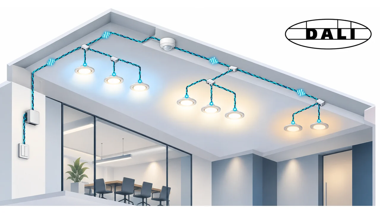
DALI (Digital Addressable Lighting Interface) is a digital protocol for lighting control, described in the IEC 62386 series. Every luminaire or driver has its own address and can be dimmed, switched on and off independently of the others. Unlike analogue 0–10 V dimming, a DALI device can also answer: report its state, a lamp failure or operating hours.
Where it is used
- Offices, schools, hospitals, shops.
- Warehouses and factory halls with daylight regulation.
- Hotels, restaurants and homes with scenes.
- Emergency lighting with automatic tests.
Basic terms
- Control gear — the driver or ballast of the luminaire. It executes commands and regulates the light.
- Control device — a push button, motion sensor, light sensor or controller.
- Application controller — the device that decides the logic: when to switch what.
- Bus (line) — the two wires that carry the data.
The physical bus
DALI uses two wires without polarity: it does not matter which is which. The nominal bus voltage is about 16 V (9.5–22.5 V allowed). It is supplied by a dedicated DALI power supply that limits current to about 250 mA. That is the total current for the whole line, not per device.
| Parameter | Value |
|---|---|
| Speed | 1200 bit/s |
| Coding | Manchester |
| Addresses per line | up to 64 |
| Groups | up to 16 |
| Scenes | up to 16 |
| Max bus current | about 250 mA |
| Voltage drop | no more than 2 V to the farthest device |
The low speed is deliberate: the bus tolerates long cables and ordinary wiring. Permissible length is set by voltage drop and cross-section. A typical guide is up to 300 m with 1.5 mm², but the exact value follows from a calculation for the actual current and cable.
Cabling
- An ordinary 230 V cable can be used. Five-core cable is common, with the two spare cores used for DALI.
- The topology is free: line, star and tree.
- No closed loop.
- No terminator is needed.
- Every driver has its own 230 V mains supply. The DALI bus does not power the lamps.
The DALI bus is not safety extra-low voltage (SELV): its insulation is rated like mains. It can therefore run in the same cable or conduit as 230 V.
Messages
The frame sent to devices (forward frame) is 19 bits: a start bit, 8 address bits, 8 data bits and two stop bits. The reply (backward frame) is 11 bits. DALI-2 adds longer frames for input devices.
Addressing
The address is 6 bits, 0 to 63, called the short address. In addition there are:
- Group address (0–15) — up to 16 groups, and one device can be in several.
- Broadcast — to all devices on the line.
Addresses are assigned during commissioning. A driver is delivered without a short address; the controller finds it by a random 24-bit "long address" and uses that to hand out short addresses. Each address is then tied to the luminaire's physical place on the plan.
Brightness
The level is 8 bits, 0 to 254. The dimming curve is logarithmic, because the eye perceives light logarithmically, so a smooth fade looks even. The lowest (minimum) and highest (maximum) levels are set separately for each driver. Fade time and fade rate are also parameters.
Scenes
Each driver can remember up to 16 levels, one per scene. A "scene 5" command to a group or the whole line brings all lamps to their stored level. One command changes the whole mood of the room.
Kinds of commands
- Direct level setting (DAPC).
- On, off, up, down, maximum, minimum.
- Recall scene.
- Queries: status, level, lamp failure, device type, version.
- Configuration: group membership, storing scenes, minimum, maximum.
DALI and DALI-2
The first version mainly covered drivers, and there was no unified description for input devices (buttons, sensors). DALI-2 is an update in which:
- driver behaviour is specified more precisely (parts 100–200);
- input devices have their own parts (series 300): push button (301), absolute input (302), occupancy sensor (303), light sensor (304);
- a line can have several control devices at once (multi-master), with collision detection;
- devices from different makers are more compatible with one another.
DALI and DALI-2 drivers can share a line. On a mixed line, check what each device supports.
Device types
| Type | Purpose |
|---|---|
| DT0 | Fluorescent lamps |
| DT1 | Emergency lighting with battery and automatic tests |
| DT6 | LED modules |
| DT7 | Switching (relay output) |
| DT8 | Colour control: colour temperature (Tc), RGB(W), xy |
DT8 gives tunable white and colour lighting over the same two-wire line.
D4i
D4i is an extension for drivers built into the luminaire. It adds a standard supply for sensors, standard access to data such as energy, operating hours and temperature, and simpler sensor installation.
Commissioning
- Run the bus and check the cables.
- Switch on lamp power and DALI power.
- Automatic search and address assignment.
- Identification: flash each luminaire to link its address with its place.
- Group by room and function.
- Set scenes, minimums and fade times.
- Assign sensors and buttons and link them to groups.
- Save the configuration and a backup of the project.
Integration
- KNX — a DALI gateway translates KNX groups and scenes to a DALI line.
- BACnet and Modbus — gateways allow supervision by the building management system.
- Smart home — some controllers present groups as ordinary lamps to smart home systems.
Comparison with other dimming methods
| Method | Strengths | Limits |
|---|---|---|
| 0–10 V | Simple to connect | One channel per luminaire, no feedback, more cables |
| Phase dimming | No control cable | LED compatibility, flicker |
| DALI | Addressing of each luminaire, feedback, scenes | Needs addressing and commissioning |
| DMX | Fast, for stage and effects | Not for general building lighting |
Typical problems
- A closed loop on the bus.
- Total current exceeded because more devices are connected than allowed.
- Excessive voltage drop on long lines with a small cross-section.
- Two drivers with the same short address after a replacement.
- DALI-2 input devices on a line whose drivers or controller do not support multi-master.
- No backup of the configuration, which makes replacing a driver harder.
In short
DALI is a good choice when lighting is grouped by function rather than by electrical circuit, when scenes and daylight regulation are needed and when feedback matters. The drawback is the commissioning effort. In new buildings DALI-2 is the best starting point, and in older installations the existing line is often kept and only the drivers are replaced.