RS-485 is not a protocol
RS-485 (TIA/EIA-485) describes only the electrical side: what voltages appear on the wires and how devices are connected. What is sent over them is decided by the protocol on top, most often Modbus RTU and BACnet MS/TP, but also many vendor protocols.
Differential signalling
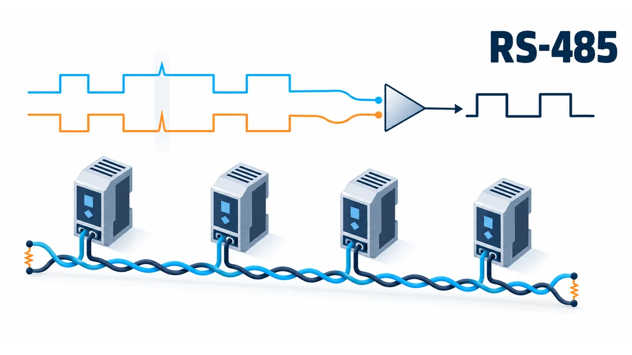
Data travels on two wires, called A and B (sometimes D− and D+). The receiver looks at the difference between them, not the voltage to ground. Noise affects both wires almost equally and cancels out, so the line tolerates long distances and industrial environments. A receiver detects a signal at a difference of about 200 mV, and the common-mode voltage may range from −7 to +12 V relative to the device ground.
Half duplex
The most common scheme is two-wire. Two wires mean only one device talks at a time. Each device's driver is off while it listens and is enabled only when it sends. This is controlled by the DE (driver enable) and RE (receiver enable) pins, often tied together. Many converters do it automatically. A four-wire variant has separate pairs for each direction.
Distance and speed
| Speed | Typical distance |
|---|---|
| up to 100 kbit/s | up to about 1200 m |
| 1 Mbit/s | about 100 m |
| 10 Mbit/s | about 12 m |
In building automation and Modbus the usual speeds are 9600–115200 bit/s, where length is rarely a problem.
Topology
A bus, not a star. The cable runs from device to device (daisy chain). Only very short stubs are acceptable. A star or long branches cause reflections and data errors.
Termination
At both ends of the bus a resistor equal to the cable's characteristic impedance is fitted, usually 120 Ω between A and B. Not in the middle and not on every device. A missing terminator at one end, or more than two, cause reflections, especially on long cable or at high speed.
Bias
When nobody is transmitting the line floats and receivers may read noise as data. So at one place on the bus (usually at the master) resistors to the supply and to ground hold the line in a defined state. At one place only, not on every device.
Cable
- A twisted pair for the signal, preferably shielded, with about 120 Ω impedance.
- The shield is grounded at one point so no current flows through it.
- A third conductor (common) is used when devices have different potentials.
- Power cable should not run parallel to the signal cable.
Most common problems
- A and B swapped. Makers label them differently. If there is no communication, swapping them is the first thing to check.
- Missing or extra terminators.
- A star-shaped cable layout.
- Too many devices. A classic receiver is 1 unit load and the line supports 32. Modern chips load the bus less and allow more.
- Different port settings: speed, parity, stop bits.
- No galvanic isolation between separate grounds.